3D Hand Visualization
The 3D panel renders hand tracking and sensor data in real-time 3D space with latency typically under 10ms. It includes three core visualization components, along with tactile point cloud and coordinate transform display.
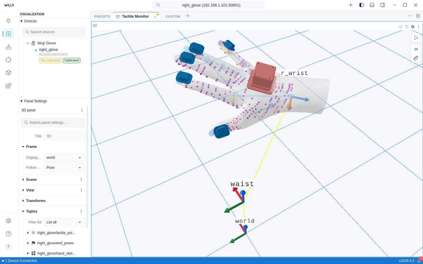
The following features are only available when a Wuji Glove is connected: hand skeleton rendering, fingertip pose visualization, EMF poses, and tactile point cloud pressure coloring.
| Component | Preview | Description |
|---|---|---|
| Hand skeleton |  | 21 MediaPipe keypoints and bone connections with per-finger confidence coloring |
| Fingertip poses |  | Position and orientation of 5 fingertips rendered as bullet-head geometry |
| EMF poses |  | Electromagnetic tracking transmitter/receiver coils with confidence coloring |
| Tactile point cloud |  | Tactile sensor pressure data rendered as colored point cloud |
| TF coordinate transforms |  | Static and dynamic coordinate transform display |
Hand Skeleton
The Hand Skeleton component renders 21 MediaPipe standard keypoints and their connections:
- Joints: Rendered as spheres, distributed across thumb (4), index (4), middle (4), ring (4), pinky (4), and wrist (1)
- Bones: 21 connections rendered as cylinders, representing the hand topology
Each joint's color reflects the finger's tracking confidence through Color Map mapping.
Configuration:
| Setting | Default | Description |
|---|---|---|
| Color Map | Safety | Color mapping scheme |
| Invert Colors | Yes | Invert the color mapping direction |
| Opacity | 0.9 | Opacity level |
| Point size | 5 mm | Joint sphere size |
| Line scale | 0.3 | Bone line width scale |
| Show Axis | Toggleable | Show coordinate axes at each joint |
| Hand Profile | wujihand | Hand model profile, with options wujihand, wujihand2, and Custom URDF |
| Custom URDF Path | — | Absolute path to a local URDF file, used by SDK-side IK when Custom URDF is selected |
Fingertip Poses
The Fingertip Poses component renders independently from the hand skeleton, displaying the position and orientation of 5 fingertips:
- Geometry: Custom bullet-head shape (ellipsoid tip + cylinder extension)
- Coordinate system: Z-axis toward wrist, X-axis from pinky to thumb, Y-axis toward dorsal side
- Supports independent toggle, can be used alongside or separately from the hand skeleton
Configuration:
| Setting | Default | Description |
|---|---|---|
| Color Map | Safety | Color mapping scheme |
| Invert Colors | Yes | Invert the color mapping direction |
| Opacity | 0.9 | Opacity level |
| Point size | 5 mm | Fingertip geometry size |
| Min Value / Max Value | 0.0 / 1.0 | Value range for color mapping |
| Show Axis | Toggleable | Show fingertip coordinate axes |
| Axis scale | 0.02 | Axis length |
EMF Poses
The EMF Poses component visualizes the electromagnetic tracking system's transmitter and receiver coils:
- Transmitter coil: Rendered at the EMF coordinate origin
- Receiver coils: Rendered at each finger's EMF sensor position
- Sensor visual: Rendered as the actual STL mesh by default. Switch to cube mode in settings
- Color reflects positioning confidence—higher confidence shows the "good" end of the colormap
- Switch colormaps from the Color Map dropdown in the Sidebar's Panel section. Defaults to Safety (Okabe-Ito), the recommended accessibility-friendly colormap for 3D visualization
Configuration:
| Setting | Default | Description |
|---|---|---|
| Color Map | Safety | Color mapping scheme |
| Invert Colors | Yes | Invert the color mapping direction |
| Opacity | 0.7 | Opacity level |
| Sensor visual | STL | Sensor render mode (STL / Cube) |
| Min Value / Max Value | 0.80 / 0.92 | Confidence mapping range |
| Show Axis | Toggleable | Show EMF coordinate axes |
| Transfer Function | — | Transfer function type |
| Gamma (γ) | Adjustable | Gamma transfer function (0.1–3.0) |
| EXP (k) | Adjustable | Exponential transfer function (0.1–10.0) |
Tactile Point Cloud
Renders tactile sensor data as a point cloud in 3D space, where each point's color reflects pressure value. Switch colormaps and adjust color mapping parameters in the Sidebar's Panel section.
TF Coordinate Transforms
The 3D view supports TF (Transform) coordinate transform display. Expand Transforms in the Sidebar's Panel section to view the transform tree, which includes static transforms (tf_static) and dynamic transforms.
Each transform can be configured with fixed offset values or subscribed to a Topic for real-time updates.
Global Topics
tf and tf_static are global Topics—subscribe to them directly without a device name prefix. When multiple devices are connected, their transform trees merge automatically into a single unified tree. This enables both hands to display simultaneously in the same 3D view. The device firmware assigns l_ and r_ prefixes to left-hand and right-hand frames automatically.