HMI User Guide
1. Launch HMI
Visit the GitHub Releases page to download the package for your platform.
| Platform | How to Launch |
|---|---|
| Windows | Extract the package, then double-click wuji-hand-hmi_<version>-windows to launch. |
| Ubuntu | 1. Install: sudo apt install ./wuji-hand-hmi_<version>_amd64.deb2. Open from the application menu, or run wuji-hand-hmi in the terminal. |
Having issues during startup? See the Troubleshooting section.
2. Panel Introduction
Wuji Hand HMI consists of Global Panel, Single-Axis Panel, and Log Panel.
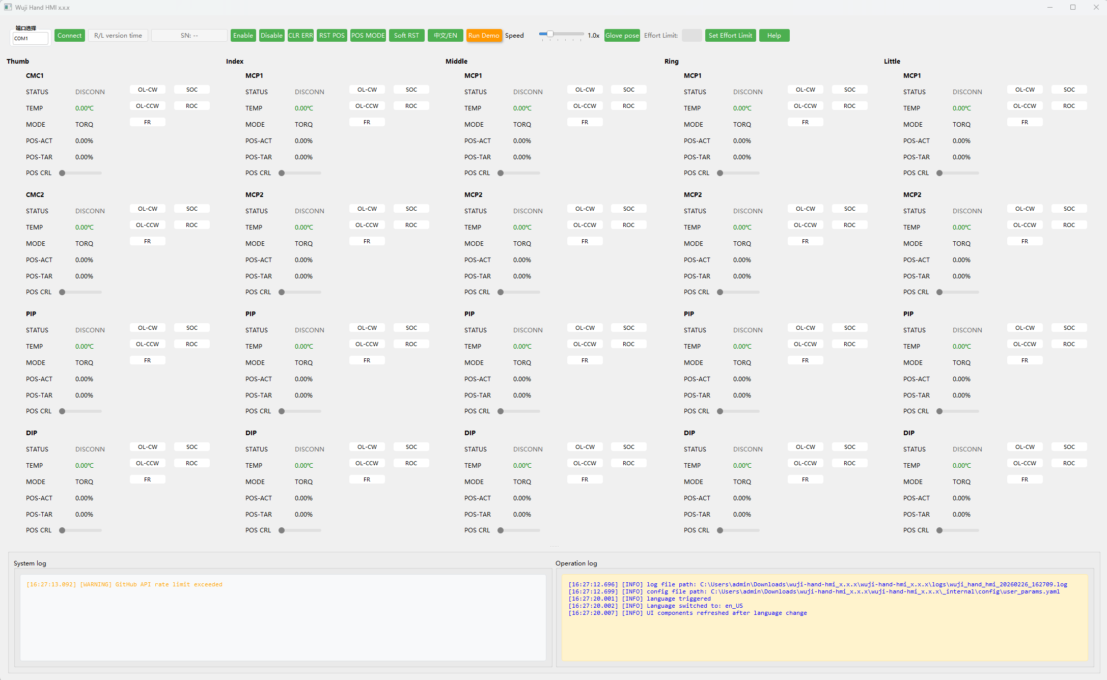
2.1 Global Panel
The Global Panel is for whole-hand operations and status viewing. It operates the entire hand, with feedback from the spinal board.

| Name | Description |
|---|---|
| Port selection | The Linux HMI auto-filters available ports. The Windows HMI doesn't filter ports automatically. Launch the HMI first, then connect the hand. Check the Log Panel Operation Log for |
| Connect / Disconn | Choose the correct port and click Connect. Click Disconn to end the session. |
| Spinal board status | Displays: Left/Right hand, system firmware version, online time, e.g. Left 1.2.0 24m59s. |
| SN | Displays the device serial number. |
| Enable | Click Enable to power all joint motors. Motor status becomes RUN. |
| Disable | Click Disable to de-energize all joint motors. Motor status becomes READY. |
| CLR ERR | If WARNING/ERROR/FATAL appears, click CLR ERR first, then try enabling again after recovery. |
| POS MODE / RST POS | Click POS MODE to set motor mode to RT_FCL. While enabled, click RST POS to return the hand to the zero pose. |
| Soft RST | Restart the driver boards. During restart, motor status briefly shows DISCONN. After completion, motor status returns to READY. |
| 中文 / EN | Toggle UI language between Chinese and English. |
| Run Demo | Click Run Demo to play a preset motion sequence for quickly verifying communication and basic motion. |
| Speed | Controls the demo playback speed multiplier. Drag the slider to adjust. Range 0.5x–3.0x, default 1.0x. |
| Glove pose | Click Glove pose to switch the hand to a posture that facilitates removing and installing soft components and gloves. |
| Effort Limit | Effort limit input field for entering the target value, used with the Set Effort Limit button. |
| Set Effort Limit | Sets the maximum effort output allowed for joints. Range 0–3.5 (A), default 1.5 (A). Enter a value in the input field and click Set Effort Limit. What is Effort? Effort is the actuation value in current space, filtered before output. It is not the actual measured current—think of it as relative actuation strength, useful for load monitoring and collision detection. Warning: Modifying Effort Limit may cause device damage Increasing effort limit raises motor output torque and increases motor heating. Damage caused by incorrect settings is the user's responsibility.
|
| Help | Click Help to open this documentation page. |
2.2 Single-Axis Panel
The Single-Axis Panel is for single-joint operations and status viewing. It operates individual joint axes, with feedback from the driver board.
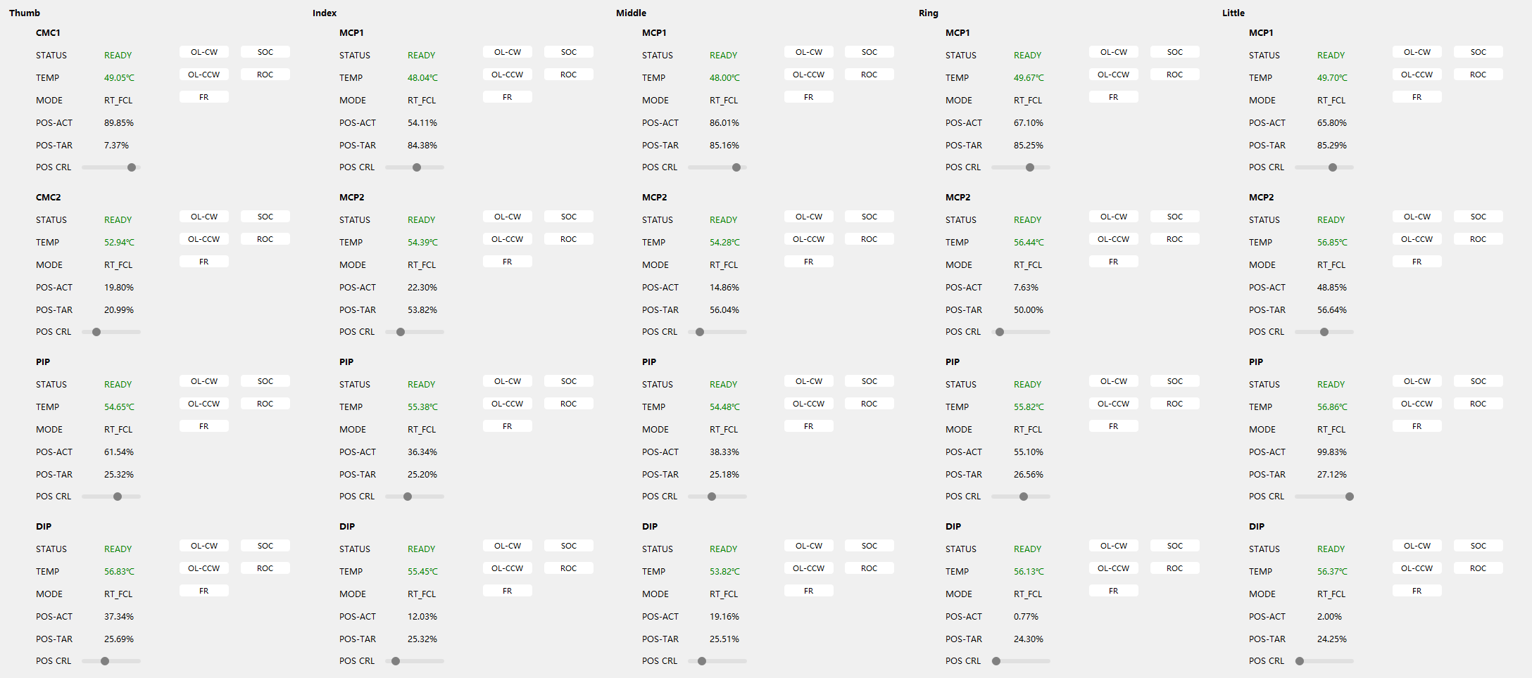
| Name | Description |
|---|---|
| Joint | Joint name. |
| STATUS |
|
| TEMP | Displays the current motor temperature. |
| MODE | Displays the current control mode, e.g. RT_FCL. |
| POS-ACT | Displays the position feedback as a percentage within the factory-calibrated travel range. |
| POS-TAR | Displays the desired position as a percentage within the factory-calibrated travel range. |
| POS CRL | When MODE is RT_FCL and STATUS is RUN, drag the slider to set the target position. |
| OL-CW / OL-CCW | Open-loop motion corresponding to clockwise/counterclockwise polarities. Press and hold OL-CW or OL-CCW to rotate the motor in one direction. |
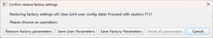
| FR | Click FR to open the factory reset dialog:
After restoring to factory settings, click Soft RST in the Global Panel for the changes to take effect.
|
| SOC / ROC | Factory zero may differ slightly from the URDF zero. For Sim2Real alignment, you can manually set a user zero close to the URDF zero.
|
2.3 Log Panel
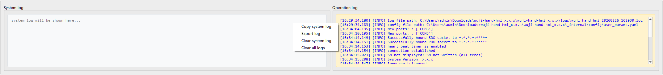
The Log Panel has two sections. The left side displays the System log, recording warnings and errors at WARNING level and above. The right side displays the Operation log, recording initialization info and user actions. Right-click in the log area to:
- Copy system log / Copy operation log: copy selected log content to the clipboard.
- Export log: package both system and operation logs for troubleshooting.
- Clear system log / Clear operation log: clear the corresponding log area.
- Clear all logs: clear both system and operation logs.
If the device or HMI malfunctions, first export logs from the Log Panel and save them. Provide the logs together with a problem description to support for faster diagnosis.
3. Connect and Enable
3.1 Device Connection
After confirming the hardware connections, launch the HMI as described in Launch HMI. On successful startup, the Log Panel Operation log shows the following messages:
[INFO] Successfully bound SDO socket to 127.0.0.1:xxxxx
[INFO] Successfully bound PDO socket to 127.0.0.1:xxxxx
[INFO] heart beat timer is enabled
[INFO] connection established
[INFO] Device SN displayed: xxxx.xxxxxx.xxx
[INFO] System Version: x.x.x
Click Connect in the Global Panel. On successful connection:
- The Spinal board status in the Global Panel displays: Left/Right hand, system firmware version, online time, e.g.
Left 1.2.0 24m59s. - The STATUS in the Single-Axis Panel shows
READY, and data such as motor temperature updates continuously.
3.2 Quick Functional Checks
Click Run Demo in the Global Panel to have the hand loop through a preset motion sequence for verifying communication and motion.
Do not perform other operations while the sequence is running.
4. Troubleshooting
4.1 Port Access Permission
If you can't find the port when launching the Ubuntu HMI:
-
Method 1: Add the current user to the
dialoutgroupsudo usermod -a -G dialout $USERAfter execution, apply the permissions:
- Current terminal only:
newgrp dialout - System-wide:
sudo reboot
- Current terminal only:
-
Method 2: Launch the HMI with sudo
sudo wuji-hand-hmi
4.2 Display Scaling Warning
If a display scaling warning appears during startup, the system display scaling ratio is greater than 100%. Adjust the display scaling to 100% (1:1) in your system settings, then restart the HMI.