Getting Started
Connection and configuration
Step 1: Connect the data acquisition board
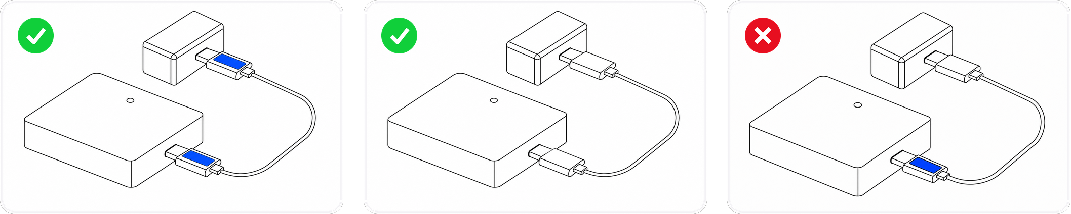
Use the USB-C to USB-C Cable to connect the data acquisition board to the USB-C to Ethernet power adapter.
Pay attention to the orientation of the USB-C to USB-C Cable. Both ends of the cable have a white rectangular label (shown as a blue block in the image below) on the same side to help you quickly identify the correct orientation. If the cable is inserted with the label side up into the data acquisition board, it must also be inserted with the label side up into the USB-C to Ethernet power adapter, otherwise it will only provide power without data transmission.
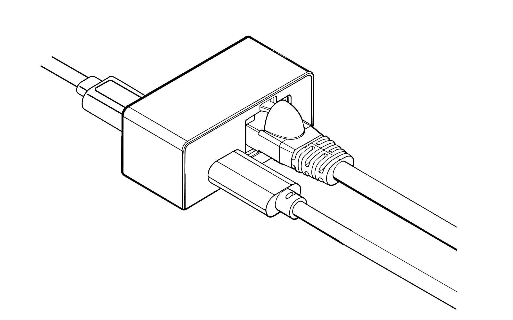
Step 2: Connect Ethernet and power
Use the USB-C to Ethernet power adapter to connect the Ethernet cable and power cable. For the power cable, we recommend a USB-A to USB-C cable.
Step 3: Configure computer network
Verify the computer and glove are on the same network segment (default segment is 192.168.1.x). The first three octets of the IP address must match, and set the subnet mask to 255.255.255.0. The default IP is 192.168.1.100 for the left hand and 192.168.1.101 for the right hand. Avoid assigning these addresses to the computer to prevent conflicts. Follow these steps to configure a static IP and subnet mask.
- The following example demonstrates connecting to the right-hand glove. Replace the interface name in the commands with your actual interface name, and adjust the IP address based on the target glove.
- This configuration is temporary and won't persist after a system reboot.
1. Identify the network interface name
ip link showFind the Ethernet interface name, for example eth0, enp3s0, or eno1.
2. Verify the Ethernet cable is connected
ethtool eth0 | grep "Link detected"The output should show Link detected: yes.
3. Clear existing IP addresses
sudo ip addr flush dev eth0This command removes all existing IP addresses from the interface. If the interface is being used for other network connections, they'll be disconnected.
4. Set a static IP and subnet mask
sudo ip addr add 192.168.1.10/24 dev eth0/24 corresponds to a subnet mask of 255.255.255.0.
5. Bring up the interface
sudo ip link set eth0 up6. Verify the IP and subnet mask
ip addr show eth0Confirm the output contains inet 192.168.1.10/24.
7. Test connectivity
# Right-hand glove example
ping 192.168.1.101
If connecting to the left-hand glove, use ping 192.168.1.100 instead. Receiving a response indicates a successful connection. You can then start using Wuji SDK or Wuji Studio.
Step 4: Wear the Wuji Glove
Put on the Wuji Glove and adjust the position of the data acquisition board using the arm strap.
When putting on or removing the glove, apply force at the palm area. Do not pull on the wrist area.

When removing the glove, apply force on the fabric at the fingertips. Do not pull on the EMF modules or the back of the hand.
Important: After wearing, before connecting to software, ensure:
- Keep fingers slightly bent in a natural, relaxed state
- Do not cross the fingertip EMF modules, do not make a fist
Safety Guidelines:
- Avoid use in humid environments
- Do not over-bend the sensor areas
- Store in a dry, cool place
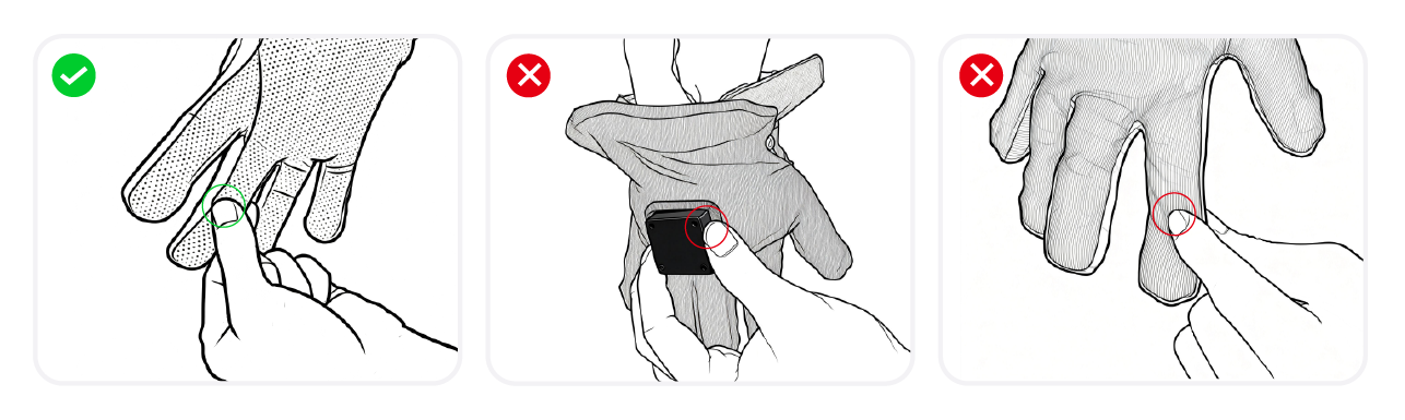
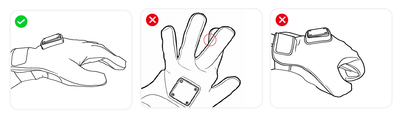
Step 5: Install the Tracker (optional)
To use an external Tracker for spatial tracking, peel back the soft cover on the EMF transmitter module on the back of the glove and mount the Tracker on the exposed mounting plate.
![]()
![]()
Different Tracker models may require different 3D-printed adapters. The wuji-description repository covers three asset classes—glove-side Tracker mounting CAD, Wuji Hand simulation models (URDF / MJCF / USD / RViz), and hand-to-arm adapters (direct / impact-resistant / Unitree G1)—all compatible with MuJoCo, Isaac Sim, and ROS2-RViz.
Software installation
After hardware setup is complete, use the following software to interact with Wuji Glove:
- Wuji Studio (Desktop visualization application) — See Wuji Studio Documentation
- Wuji SDK (Python development kit) — See Wuji SDK Documentation